Why Choose Small hard alloy pad Welding Technology in Decanter Centrifuges?
Comparison of Wear-Resistant Technologies Among Major Brands
| Brand | Gasket Welding | Alternative Technology | Application Areas |
|---|---|---|---|
| ANDRITZ | ✅ Yes | Small tungsten carbide gaskets | Municipal, Biomass, Chemical |
| Flottweg | ✅ Yes (some models) | Replaceable liner + welded gasket modules | Hazardous waste, Mineral processing |
| Alfa Laval | ❌ No | Zirconia ceramic covering | Food, Marine, Mining |
| Westfalia | ❌ No | Ceramic coating, Alloy inlay | Pharmaceuticals, Fine chemicals |
| Pierre Reis | ❌ No | Carbide spraying + Alloy spiral | Mining, Oil drilling |

Key Benefits of Small Wear-Resistant Pads
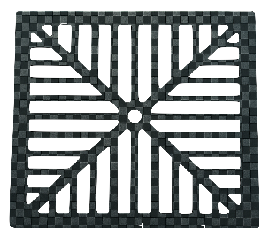
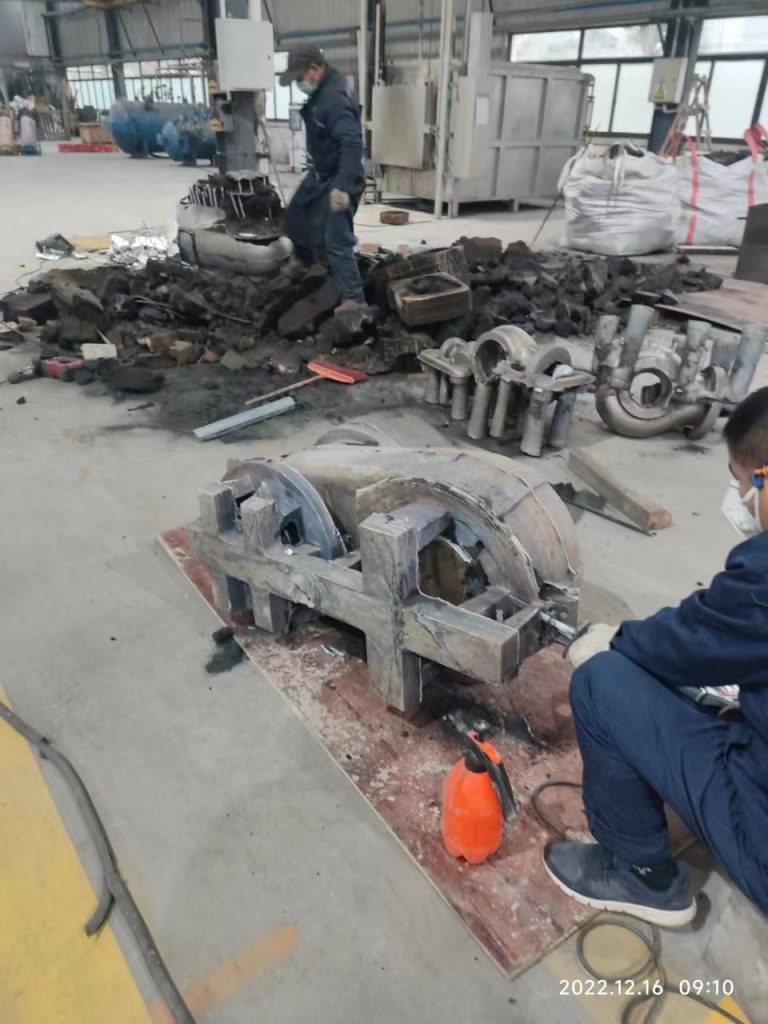
The spiral blades in decanter centrifuges are exposed to intensive abrasive wear due to continuous contact with solid particles such as:
- Mineral fines
- Crystalline salts
- Biomass residues
- Metal fragments
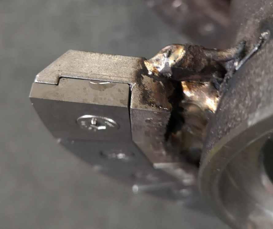
Welding small carbide pads to the screw conveyor blades addresses these issues effectively.
Advantages Include:
- ✅ Superior Abrasion Resistance: Protects against high-hardness materials in contact zones.
- ✅ Reduced Maintenance: Sacrificial pads absorb wear, protecting the main spiral blade.
- ✅ Extended Equipment Life: Delays the need for expensive part replacements.
- ✅ Lower Downtime: Minimizes operational interruptions due to wear-related failures.
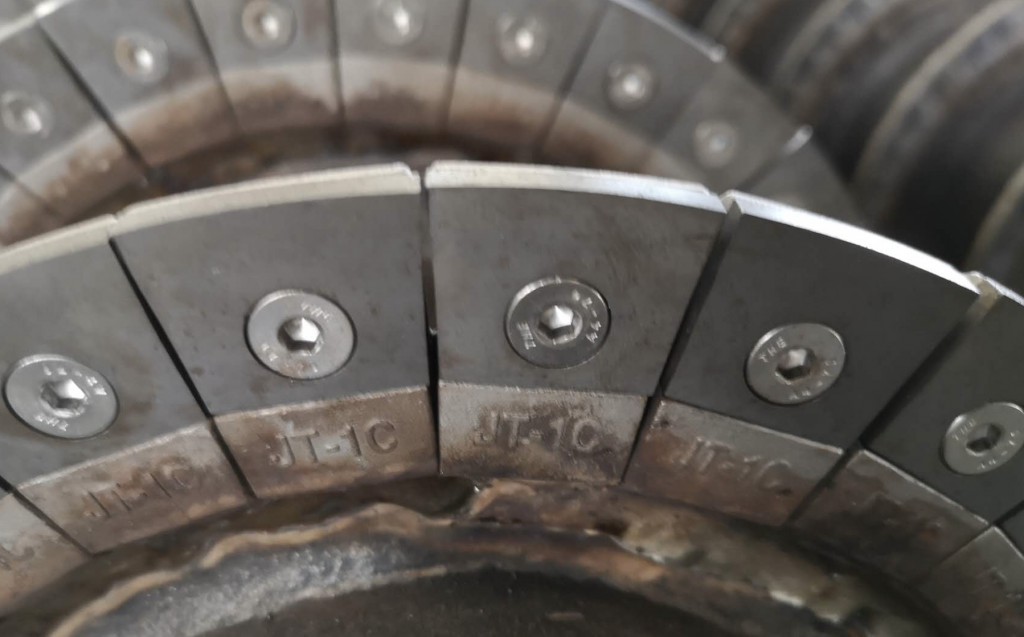
Why Weld Multiple Small Gaskets Instead of One Large Plate?
- Adapts to Complex Curved Surfaces: Easier installation on helical blade geometries.
- Distributes Stress & Impact: Reduces crack risk due to thermal/mechanical stress.
- Simplified Maintenance: Damaged gaskets can be selectively replaced.
- Enhanced Welding Quality: Smaller weld zones improve structural integrity.
- Cost-Effective Over Time: More targeted protection with reduced material waste.

Case Studies: Brands Utilizing Gasket Welding
ANDRITZ
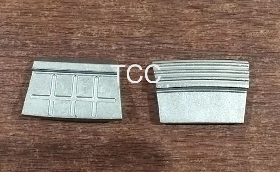
- Technology: Dense welding of small tungsten carbide gaskets (10–20 mm) on blade surfaces.
- Advantages: Excellent coverage of high-wear areas, replaceable modules, strong substrate bonding.
- Use Cases: Municipal sludge, biomass waste, chemical sludge.
Flottweg
- Technology: Modular wear liners with welded carbide blocks or strips.
- Advantages: Dual protection (liner + gasket), high replacement efficiency.
- Use Cases: Hazardous industrial waste, mineral tailings.
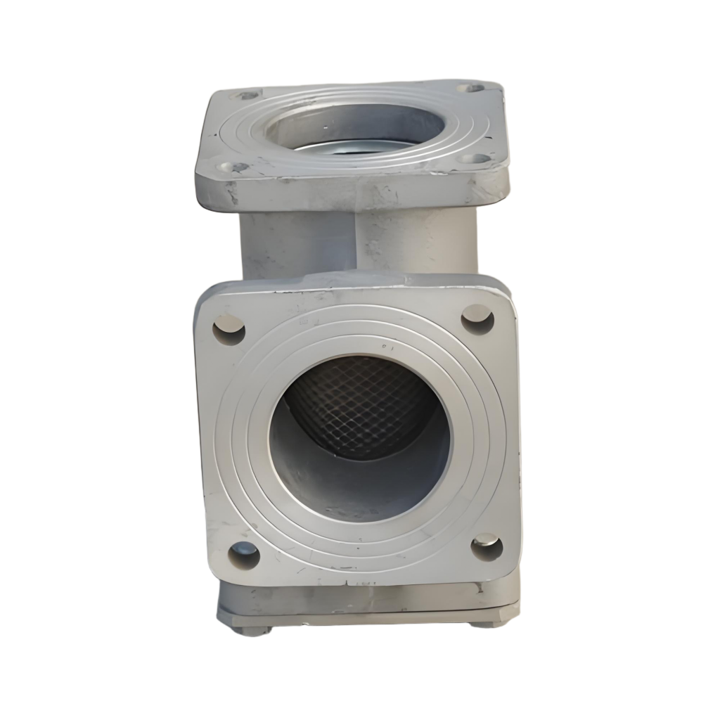
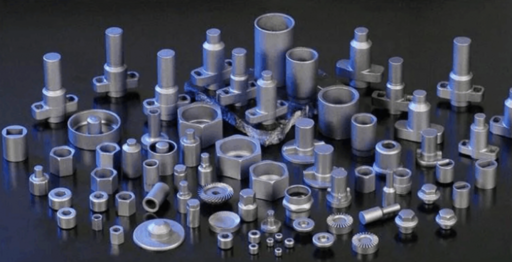
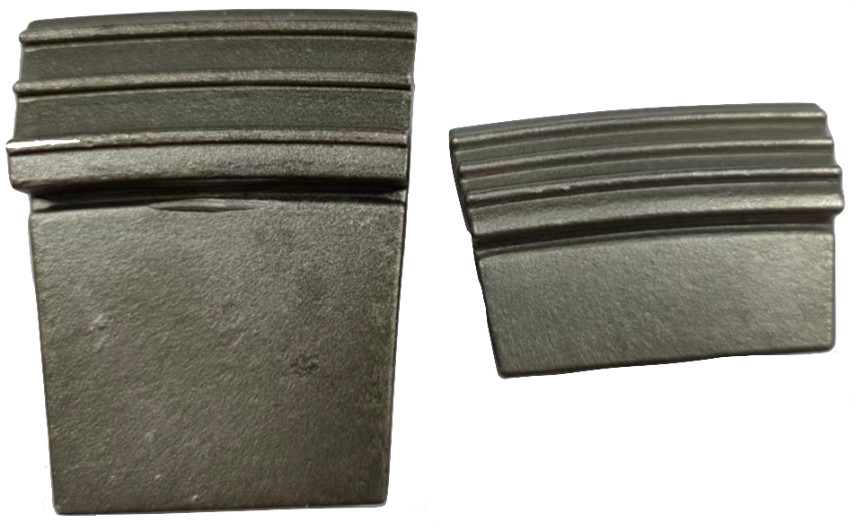
TCC’s Contribution: Custom Casting & Welding of Carbide Gaskets
TCC Co., Ltd specializes in producing high-quality cast carbide gaskets, supporting welding services with strong material compatibility.
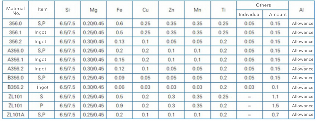
Materials Commonly Used:
| Material | Key Feature | Typical Application |
|---|---|---|
| Tungsten Carbide (WC-Co) | Ultra-hard, durable | Mineral wear, solids processing |
| Chromium Carbide (Cr₃C₂) | Corrosion-resistant | Chemical and biomass slurry |
| NiCr-Si-B Alloys | Weldability, thermal match | Stainless steel blades, uniform stress |
| Cermet | Thermal shock resistance | High-temp drying, crystallization |
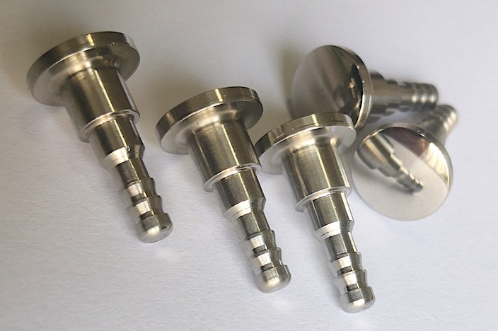
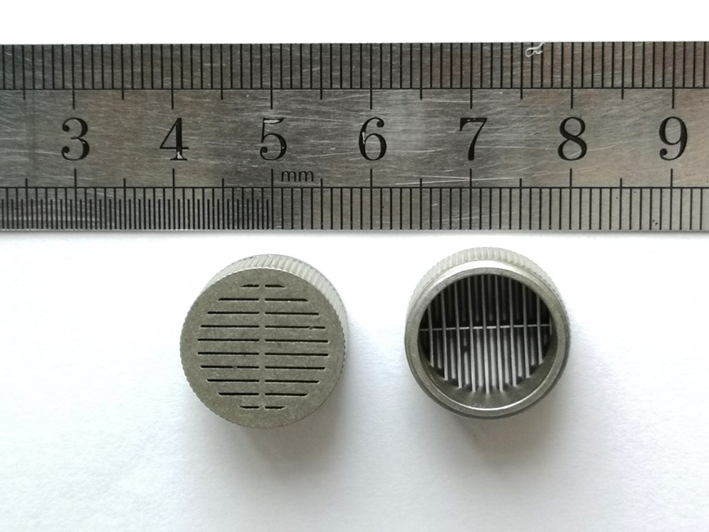
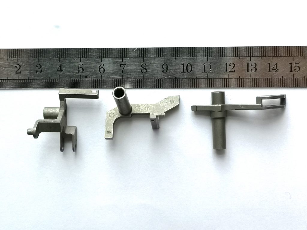
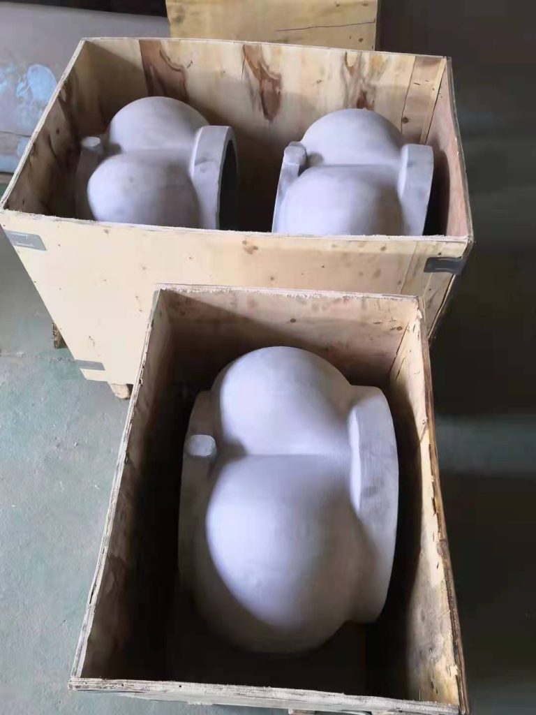
Advantages of Cast VS Machined Gaskets
- Complex Shapes in One Step: Cast gaskets fit curved surfaces more naturally.
- Material Gradient Design: Can embed cores with different thermal/mechanical properties.
- Scalable Cost: Casting becomes economical for high-volume, high-alloy content parts.
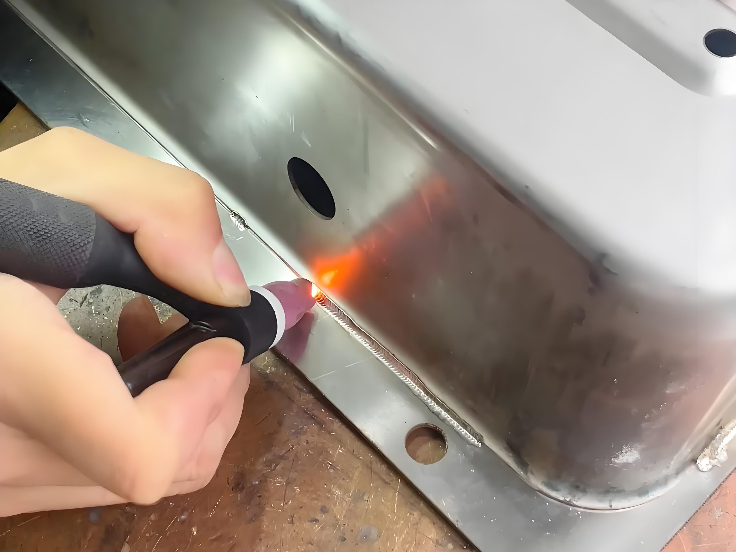
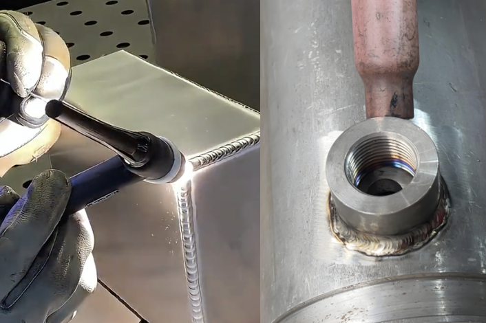
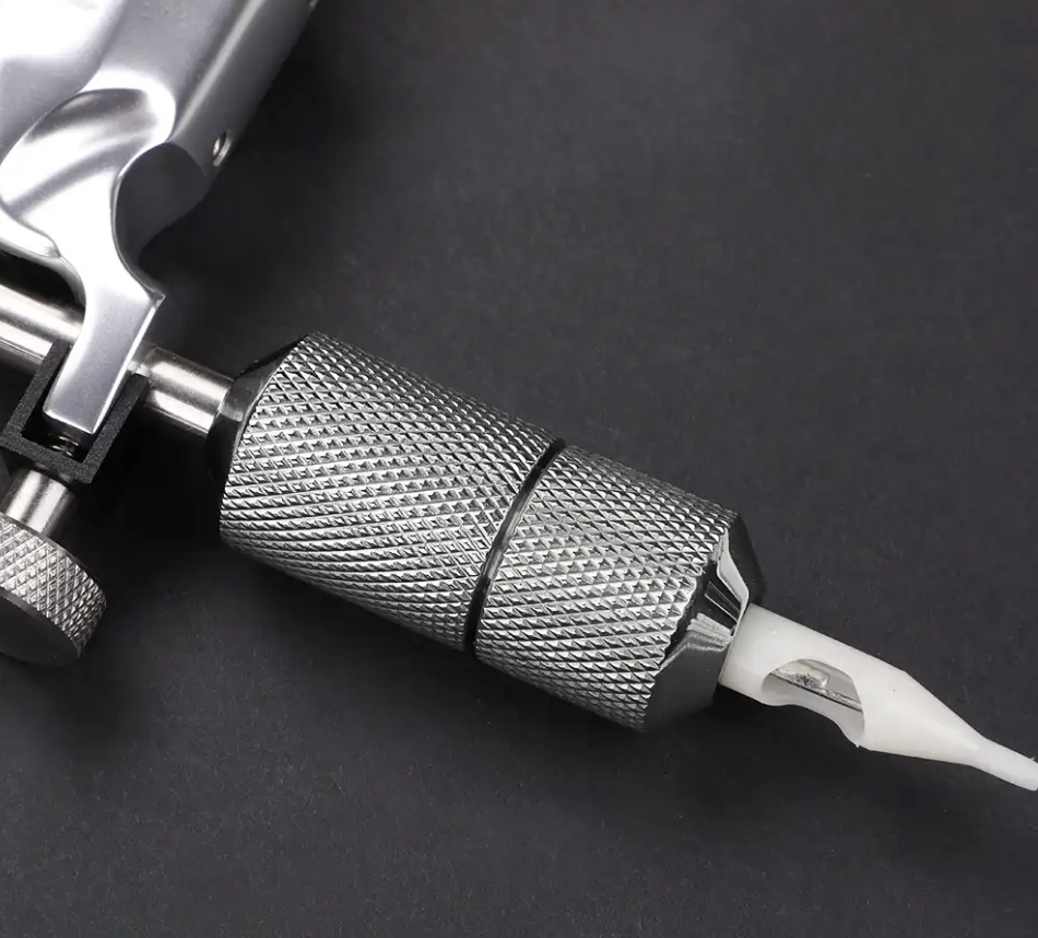
Welding Methods and Process Control
Common Welding Techniques:
- Brazing: For low-stress or smaller parts; uses Ni or Ag-based filler.
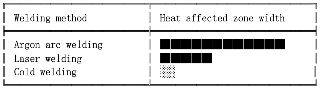
- Plasma Arc / Laser Welding: Precision, low distortion, ideal for thin blades.
- Surfacing + Composite Welding: For enhanced impact and wear performance.
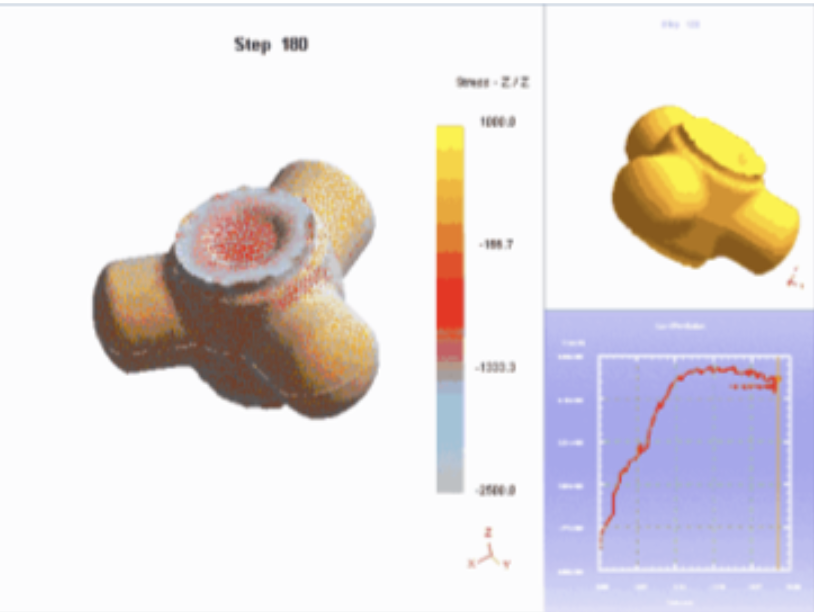
Process Control Tips:
- Preheat and slow cooling to reduce cracking risk.
- Maintain strong fusion and proper weld penetration.
- Use staggered multi-point welding to minimize distortion.
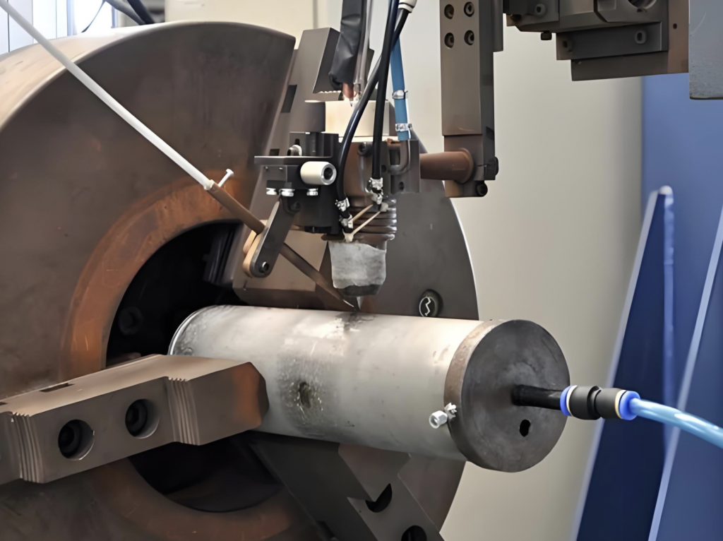
Industry Trends
- 📌 Standardized modular gasket systems are gaining popularity.
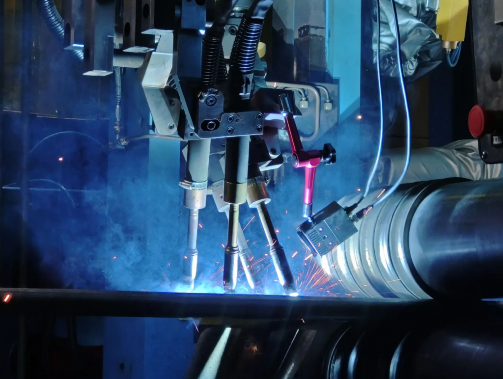
- 🤖 Asian manufacturers have adopted automated gasket welding machines.
- 🔍 Smart monitoring systems now provide wear tracking and replacement recommendations.
Conclusion
The welding of small wear-resistant carbide pads onto decanter centrifuge spiral blades is a technically efficient, cost-effective, and scalable solution for industries facing harsh abrasive environments. TCC offers robust capabilities in casting, material matching, and welding—making it a reliable partner in extending the life and performance of high-value rotating equipment.