AlMg5Si (common grades such as EN AC-51400 or AlMg5Si1 ) It is a typical aluminum-magnesium-silicon casting alloy with excellent corrosion resistance, medium strength and good weldability , and is widely used in many industrial fields.
1. Main application areas and typical parts of AlMg5Si castings :
1. Shipbuilding and marine engineering
- Hull structural parts (hatch covers, handrails, trusses, etc.)
- Deck equipment (bases, housings, connections)
- Offshore platform structures
Reason: Excellent seawater corrosion resistance, suitable for humid or salt spray environment.
2. Transportation (especially rail and commercial vehicles)
- Railway vehicle body structure
- Automobile chassis components (subframes, wheels, brackets)
- Trailer structural parts
Reason: Higher strength-to-weight ratio and impact resistance.
3. Energy and power equipment
- Wind turbine cabin structural parts
- High voltage switch housing, electrical connectors
Reason: Certain strength, conductivity and corrosion resistance are required.
4. Building and structural parts
- Curtain wall connection components
- Aluminum formwork support system
5. Mechanical equipment
- Pump body, housing
- Industrial automation equipment parts
2. Characteristics and key points of AlMg5Si casting process
Compared with other cast aluminum alloys (such as AlSi7Mg , AlSi10Mg , AlCu4Ti , etc.), AlMg5Si has the following characteristics and points for attention during melting , pouring and solidification :
1. The oxide film is highly sensitive and requires a good protective atmosphere
- The magnesium content is high and it is easily oxidized during the smelting process to form MgO .
- Recommended use Inert gas protection (such as Ar ) or flux protection , especially during smelting and sub-packaging.
2. Strong air absorption, easy to produce pinholes
- Mg reacts with hydrogen to increase the tendency to getter, thus:
- Refining degassing (such as rotor degassing, Ar /Cl composite gas) must be sufficient ;
- Melt processing should be carried out at low temperatures ( 690–720°C is recommended ) to avoid excessive temperatures that promote aspiration.
3.High requirements for the mold (mold)
- The tendency of thermal cracking is relatively large, and the mold design should consider:
- Reasonable cooling system distribution
- Avoid combining thick sections with fast shrinking areas
4. The cooling rate needs to be controlled during the crystallization process
- AlMg5Si alloy has a wide solidification range (about 30–40°C ) and shrinkage should be avoided:
- Reasonable setting of gate system and riser
- Sequential solidification control or pressure consolidation techniques can be used when necessary
5. Post-processing heat treatment methods are limited
- T6 heat treatment (such as quenching + aging) is usually not possible because its strengthening mechanism mainly relies on solid solution rather than precipitation hardening;
- Generally adopted Use in T5 or natural aging ( F ) state .
Summary of key comparisons :
| Process | AlMg5Si Features | Differences from other aluminum alloys (such as AlSi10Mg ) |
| Melting protection | Easy to oxidize, absorb | High magnesium content → more inert gas protection is needed |
| Degassing treatment | Hydrogen removal refining is required | Stronger than normal air intake AlSi Tie |
| Casting system | Sequential solidification design required | Easy to shrink and uneven cooling has a great impact |
| Heat Treatment | T6 is usually not performed | Not suitable for precipitation hardening |
The following are The recommended parameters of AlMg5Si casting process are suitable for process scenarios dominated by gravity casting (sand mold, metal mold). It is also suitable for low-pressure casting, such as when higher density is required for the production of structural parts.
1. Melting and insulation
| Project | Recommended parameters | Illustrate |
| Melting temperature | 700–740 °C | Avoid excessive temperatures to reduce oxidation and aspiration |
| Insulation temperature | 690–710 °C | Long-term heat preservation requires protective atmosphere or flux |
| Protection method | Argon, nitrogen or flux ( NaCl+KCl ) | Prevent magnesium oxidation |
| Degassing treatment | Ar+ Cl₂ Or degas the rotor for 10–20 minutes | Control hydrogen content ≤0.15 ml/100g Al |
| Flux Recommendation | Special magnesium aluminum alloy flux, such as Foseco MTS 158 | Anti-oxidation, anti-inclusion |
2. Pouring
| Project | Recommended parameters | Illustrate |
| Pouring temperature | 710–730 °C (sand mold) 690–710 °C (Metal Type) | Fine-tune according to mold material and wall thickness |
| Mold preheating temperature (metal mold) | 250–300 °C | Prevent cold shut and poor filling |
| Gate design | Bottom injection, flow rate control, sequential solidification | Reduce oxidation slag and shrinkage |
| Riser / Feeding System | It is necessary to set up a heat preservation cap or pressurized shrinkage compensation | The alloy has a wide solidification range and large shrinkage |
| Cooling control | Local chilling iron assisted solidification control | Prevent thermal cracking and shrinkage |
3. Heat treatment recommendations
| Heat treatment status | Recommended parameters | Illustrate |
| T5 (artificial aging after casting) | 160–180 °C × 5–8 hours | Improved stability, slightly increased strength |
| F (Not heat treated ) | – | Supplied in normal condition, maintain ductility |
| T6 heat treatment is not recommended | Easy to deform, no obvious reinforcement | Because its strengthening mechanism does not rely on precipitation phase |
4. Reference values of cast properties (for comparison only)
| Performance Indicators | Numerical range | Condition |
| Tensile strength (Rm) | 180–250 MPa | Cast or T5 |
| Yield strength (Rp0.2) | 90–160 MPa | |
| Elongation (%) | 5–12% | |
| hardness | HB 50–80 | |
| density | 2.64–2.66 g/cm³ |
5. Precautions & Process Optimization Suggestions
- Do not use iron tools to stir for a long time : high-magnesium aluminum alloys are prone to inclusion reactions;
- The pouring system must be designed with an anti-eddy current structure to avoid inclusion of oxide film;
- The mold or cavity should be kept dry to prevent explosion or holes;
- Local reinforcement areas can be assisted by chill iron / pressurization to improve density .
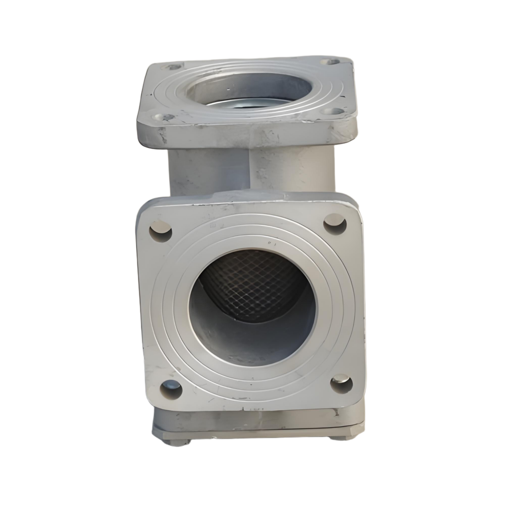
against AlMg5Si is used for fire protection system parts (such as joints, flanges, housings, connectors, etc.) The riser size design suggestions and filling simulation scheme can be divided into two parts:
1. Riser design suggestions (mainly for gravity casting)
Fire protection system parts usually require No leakage, no shrinkage, high density , so the riser design must consider the following points:

1. Riser design principles
| Project | Recommendations |
| Riser position | Place in the last solidification area of the part (usually at the top of a thick section) |
| Riser shape | Cylindrical or oval (easy to process) |
| Insulation treatment | Insulation riser sleeve + insulation covering agent |
| Feeding efficiency requirements | ≥30% and has a sequential solidification path |
| Is the riser open? | Generally use open risers unless the pressure difference is well controlled |
2. Riser size estimation method (based on Chvorinov’s law)
use Modulus Method ) Design riser :
- Modulus M ( Modulus ) = V / A
- V = volume ( cm³ )
- A = heat dissipation area in contact with air or die ( cm² )
Recommended size relationship:
Notice : The riser should use an insulating sleeve (such as an Exothermic sleeve ) to increase the effective shrinkage compensation volume by 30–50% .
3. Riser neck connection design
| Parts module M ( cm ) | Riser modulus (need to be ≥ 1.2×M ) | Typical riser diameter × height ( mm ) |
| M = 1.0 | ≥1.2 | Ø30 × 35 |
| M = 1.5 | ≥1.8 | Ø45 × 50 |
| M = 2.0 | ≥2.4 | Ø55 × 60 |
| M = 2.5 | ≥3.0 | Ø65 × 70 |
- The riser neck (the part connecting the riser to the casting) needs to be controlled to solidify slowly , with a modulus slightly lower than the riser but higher than the thickness of the casting.
- Recommendation: Neck diameter = 1.2-1.5 times the wall thickness of the part , and the length should be controlled between 20-40mm to facilitate cutting.
2. Filling and solidification simulation scheme (simulation ideas)
It is recommended to use MAGMASOFT® or ProCAST ® For numerical simulation, the following are the simulation parameters for typical medium – sized flange joints (wall thickness 10-15mm ) in fire protection systems :
1. Simulation target
- Confirm whether the solidification path is sequential
- there porosity ?
- Whether inclusions are generated ( Oxide Trap )
- Is it cold shut or insufficient filling?
2. Simulation setup recommendations
| Parameters | Setting suggestions |
| Alloy Model | AlMg5Si (user defined or input data via thermal analysis) |
| Wall Thickness Area Mesh | ≤1.5 mm grid accuracy |
| Pouring temperature | 710 °C (metal type) or 730 °C (Sand mold) |
| Mold temperature | 250 °C starting |
| Gate speed | 0.3–0.8 m/ s (to prevent air entrainment ) |
| Cooling method | Local chilling (set temperature boundaries to 50–80°C ) |
| Riser heat balance setting | Enable the insulation sleeve data parameters to simulate the delayed solidification effect of the riser |
3. Output analysis key diagram:
- Solidification Time distribution diagram → Determine the solidification order
- Porosity Map → Check whether the shrinkage compensation is successful
- Velocity Field diagram → Analyze the filling path
- Oxide Formation → Determine whether to switch to the bottom injection channel system
Conclusion Recommendation
- For fire protection flange parts, using Ø50×60mm insulation riser + symmetrical arrangement of chillers can effectively compensate for shrinkage;
- For large size connectors or housings, it is recommended to use Top injection + double riser system , with internal riser if necessary;
- 2-3 times of scheme comparison and optimization in the early stage of development (different gate / riser combinations can be set);
- If the casting is large and the thickness varies greatly, consider using Low pressure casting + local cooling channels optimize density.